


DEFINITY Enterprise Communications Server Release 8.2
Upgrades and Additions for R8r
555-233-115
Issue 1
April 2000
Multicarrier G2 Universal Module to R8r EPN
5-55High Reliability
5
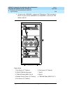
Install Circuit Packs
1. Install the new Release 8 control circuit packs into carrier “A.” Use the new
label and the annotated “list configuration all” (provided with the Release
8 removable media) as a guide.
NOTE:
Currently, the TN768 Tone-Clock circuit pack resides in a port slot of
the universal module being upgraded. Relocate this circuit pack to
the “TONE CLOCK” slot of carrier “A.” Lucent Technologies
recommends that you upgrade to the TN2182 Tone-Clock.
2. Install circuit pack blanks in slots not equipped with circuit packs.
3. For a directly-connected high reliability Release 8 system with 2 port
networks, ensure the PPN and this EPN are both equipped with a TN776
or TN570 Expansion Interface circuit pack.
For a directly-connected system with 3 port networks, ensure that the PPN
and each EPN have two TN776 or TN570 circuit packs.
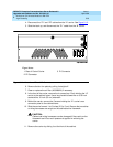
Interconnect Port Networks — High Reliability
Fiber optic cabling terminated to 9823A lightwave transceivers can interconnect
PNs up to 4,900 feet (1493 m) apart. Fiber optic cabling terminated to 9823B
lightwave transceivers can interconnect PNs up to 25,000 feet (7620 m) apart. A
300A fiber optic lightwave transceiver can interconnect PNs up to 115,000 feet
(21.7 miles, 35 km) apart.
NOTE:
These distance limits are approximate measurements of the
actual
fiber
right-of-way (not of the shortest linear distance) between the 2 endpoints.
NOTE:
It is important to label every cable that you install.
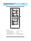
NOTE:
Keep track of which fiber attaches to which connector on each lightwave
transceiver. This section provides figures offering the suggested way of
making these connections.
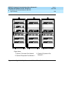
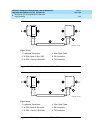
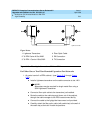
The connectors on the lightwave transceivers are labeled either “TX”
(transmit) or “RX” (receive), while the fibers attaching to each connector are
numbered either “1” or “2.” A viable fiber connection is only made when
both fibers in each cable (“1” and “2”) route from the “TX” connector of a
port network to the “RX” connector of its adjacent port network. See
Figure
5-16.
NOTE:
When finished, refer to Appendix A, ‘‘Fiber Link Administration’’ to
administer the fiber links.