


DEFINITY Enterprise Communications Server Release 8.2
Upgrades and Additions for R8r
555-233-115
Issue 1
April 2000
Fiber Link Administration
A-3Administer Fiber Links
A
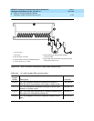
Administer Fiber Links on Simplex Systems
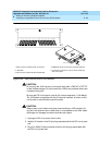
Administer the TN570 Expansion Interface and the TN574 or TN1654 DS1
Converter circuit packs.
1. Type
change circuit packs
and press
Enter. Scroll through the pages on
the form until the carrier containing the new circuit packs displays on the
screen.
2. Enter the circuit packs into the appropriate slot locations on the form.
Press
Enter when finished.
3. Type
list fiber
and press
Enter. All administered fiber connections display.
4. If a previously used fiber link is to be reused, enter
add fiber
<
number
>
and press
Enter. If this is a new fiber link, type
add fiber next
and press
Enter. The Fiber Link Administration screen appears. Each fiber link is
identified by a fiber number.
a. Type
y
or
n
in the field
Is one endpoint remoted via DS1
Converter complex?
and press
Enter.
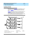
b. Enter the location of the TN570 and the TN574 or TN1654 circuit
packs for both ENDPOINT-1 and ENDPOINT-2.
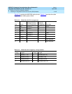
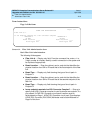
c. Scroll to page 2 of the form. Enter
y
as applicable, in each
Facility Installed?
field (A, B, C, and D).
d. In the
Bit Rate:
field, type either
1.544
(T1) or
2.048
(E1).
e. Enter the idle code in the
Idle Code MSB (1) . . . . LSB
(8):
field. The default value is
11101000
. It is recommended that
the default value be used unless it becomes absolutely necessary
to change it. The “MSB” means Most Significant Bit, the “LSB”
means Least Significant Bit.
f. In the
Line Coding:
field, enter the line coding information. This
information should match the line coding of the facility. For T1,
example line coding is
b8zs
. For E1, example line coding is
hdb3
.
NOTE:
If this data is not correct, wideband errors (multimedia call
handling) may occur.
5. For T1 sites, refer to ‘‘T1 Installations Only’’
. For E1 sites, refer to ‘‘E1
Installations Only’’.