


DEFINITY Enterprise Communications Server Release 8.2
Upgrades and Additions for R8r
555-233-115
Issue 1
April 2000
Adding or Removing Cabinet Hardware
6-105Add a Switch Node Carrier (Standard Reliability)
6
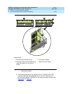
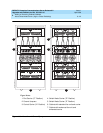
4. Behind port carrier B of each EPN cabinet:
a. Install a lightwave transceiver on cable connector at slot 1B02.
b. Connect the other end of the fiber optic cable to the lightwave
transceiver, just installed.
c. Carefully attach the fiber optic cable (with cable ties) to the wall of
the cable tray at the built-in cable-tie positions.
d. Coil up the surplus length of fiber optic cable, and carefully attach
the coil to the wall of the cable tray.
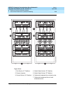
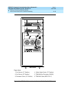
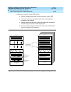
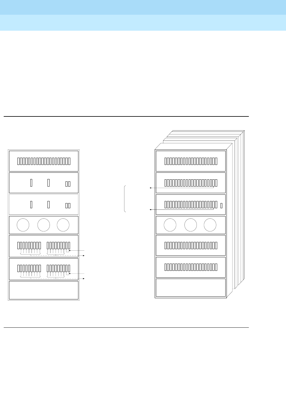
Figure 6-37. Critical-Reliability Fiber-Optic Connections through Center Stage Switch
20
19 18 17 16 1514 1312
11
10987654321
PORT CARRIER - J58890BB
CLOCK
CONTROL CARRIER - J58890AP
AUX
TERMINAL
CLOCK
CONTROL CARRIER - J58890AP
AUX
TERMINAL
FAN FAN FAN
SWITCH NODE CARRIER - J58890SA
21
20
19 18 1716 151413 9 8 7 6 5 4 3 2 1
POWER DISTRIBUTION
UNIT
20
19 18 17 16 1514 1312
11
10987654321
PORT CARRIER - J58890BB
20
19 18 17 16 1514 1312
11
10987654321
PORT CARRIER - J58890BB
EXPANSION CONTROL CARRIER - J58890AF
AUX
TERM
19 18 17 16 1514 1312
11
10987654321
FAN FAN FAN
20
19 18 17 16 1514 1312
11
10987654321
PORT CARRIER - J58890BB
20
19 18 17 16 1514 1312
11
10987654321
PORT CARRIER - J58890BB
POWER DISTRIBUTION
UNIT
SWITCH NODE CARRIER - J58890SA
21
20
19 18 1716 151413 9 8 7 6 5 4 3 2 1
B
A
C
REAR VIEWREAR VIEW
B
A
C
E
D
CABINET 1
PPN W/ONE DUPLEX SWITCH NODE
CABINET 2 THRU 16
EPN
E
D
TO CABINET 2 THRU 16, B2
TO CABINET 2 THRU 16, A1
TO CABINET 1, D3-D20
TO CABINET 1, E3-E20
BOTH CONNECTIONS FROM EACH
EPN MUST GO TO THE SAME
SLOT NUMBER (E.G. EPN
CABINET 2, 2A1 TO 1E3 AND
AND CABINET 2, 2B2 TO 1D3).
ADD IN ALTERNATING
ORDER: 20, 3, 19, 4,
18, 5, ETC.
ADD IN ALTERNATING
ORDER: 20, 3, 19, 4,
18, 5, ETC.
H600-278
H600-278
EI EI