


DEFINITY Enterprise Communications Server Release 8.2
Upgrades and Additions for R8r
555-233-115
Issue 1
April 2000
Fiber Link Administration
A-7Administer Fiber Links
A
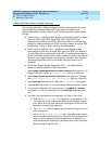
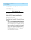
T1 Installations Only
1. The
Framing Mode:
field is display only and shows the hardware setting.
2. The
DS1CONV-1 Line Compensation:
and the
DS1CONV-2 Line
Compensation:
fields are display only and show the hardware setting.
3. In the
Facility A Circuit ID:
field, enter an optional facility name
that is unique to each facility (up to 40 alphanumeric characters). Press
Enter.
4. A display similar to the following appears after the fiber link administration
is completed:
RESET PORT-NETWORK 2 LEVEL 2 (COLD) PERFORMED
.
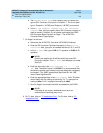
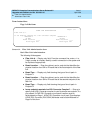
E1 Installations Only
1. Type
y
or
n
in the
CRC?
field. The “CRC” means Cyclic Redundancy
Check. This is an error detection algorithm.
2. The
Line Termination:
field is display only. A 75 (75 Ohms) or 120
(120 Ohms) typically displays.
3. In the
Facility A Circuit ID:
field, enter an optional facility name
that is unique to each facility (up to 40 alphanumeric characters). Press
Enter.
4. A display similar to the following appears after the fiber link administration
is completed:
RESET PORT-NETWORK 2 LEVEL 2 (COLD) PERFORMED
.
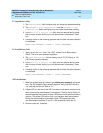
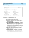
All Installations
1. When the system reset is finished, type
status port-network 2
and press
Enter. The Port Network Status screen appears. Verify that PNC Active is
“up” and that the Service State is “in.”
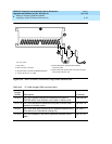
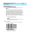
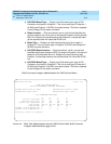
2. A Span LED, on the front of the DS1 Converter circuit pack, must be on for
each active facility administered. For example, if Facility A and Facility B
are administered, then the top 2 Span LEDs on the circuit pack must be on
(yellow). The yellow LEDs are on only if no problems were encountered
during the administration of hardware. Span LEDs associated with
non-administered facilities (C and D, in this example) should be off.
3. Perform a test call, if desired.