


DEFINITY Enterprise Communications Server Release 8.2
Upgrades and Additions for R8r
555-233-115
Issue 1
April 2000
Adding or Removing Cabinet Hardware
6-118Add a Switch Node Carrier (High or Critical Reliability)
6
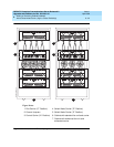
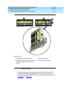
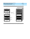
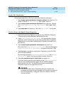
10. If a switch node carrier is being installed in the “D” position of an EPN,
verify that the ZAHF4 TDM/LAN bus terminator is installed at slot “02” of
expansion control carrier “A”. See
Figure 6-42
.
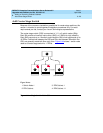
If a switch node carrier is being installed in the “E” position of an EPN,
verify that the ZAHF4 TDM/LAN bus terminator is installed at slot “21” of
port carrier “D.”
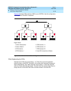
For a PPN, install the ZAHF4 TDM/LAN bus terminator at slot “01” of switch
node carrier “E.”
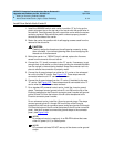
11. Install the front trim plates on the “D” carrier.
12. Install the new power units into the carrier. One 649A is installed on the left
and right sides of the carrier.
13. Connect the power cords to the power units. The power cords are the
white cables equipped with plugs that are run through the slots in the front
of each carrier.
Install Circuit Packs
1. Install the new circuit packs into carrier “D.” Use the decal and the
upgrade configuration document (provided with the equipment) as a
guide.
2. Install circuit pack blanks in slots not equipped with circuit packs.
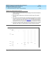
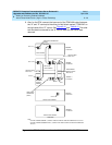
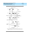
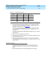
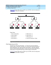
Table 6-10. TDM/LAN Connections
“J” Number Carrier Type LHS Slot RHS Slot
J58890BB L1 Port 21 02
J58890BB L2 Port 21 01
J58890BB L3 Port 21 01
J58890AP Control 21 02