


CHAPTER 6 PERIPHERAL HARDWARE FUNCTION
100 User’s Manual U10676EJ3V0UM
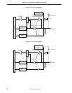
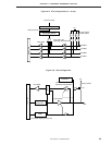
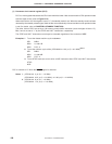
6.1.5 Connecting pull-up resistor
Each port pin of the
µ
PD754244 can be connected to a pull-up resistor. Some pins can be connected to a pull-
up resistor via software and others can be connected by a mask option.
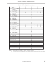
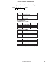
Table 6-4 shows how to specify the connection of the pull-up resistor to each port pin. The pull-up resistor is
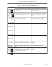
connected via software in the format shown in Figure 6-11.
The pull-up resistor can be connected only to the pins of ports 3, 6, and 8 in the input mode. When the pins are
set to the output mode, the pull-up resistor cannot be connected regardless of the setting of POGA and POGB.
Table 6-4. Specifying Connection of Pull-up Resistor
Port (Pin Name) Specifying Connection of Pull-up Resistor Specified Bit
Port 3 (P30-P33) Connection of pull-up resistor specified in 4-bit POGA.3
Port 6 (P60-P63)
units via software
POGA.6
Port 7 (P70-P73) Connection of pull-up resistor specified in 1-bit —
units by mask option
Port 8 (P80-P83) Connection of pull-up resistor specified in 1-bit POGB.0
units via software
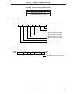
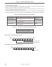
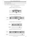
Figure 6-11. Format of Pull-up Resistor Specification Register
Specification
0 Pull-up resistor not connected
1 Pull-up resistor connected
Pull-up resistor specification register group A
765432
10
––PO3 –––PO6–
Address
POGA
FDCH
Symbol
Port 3 (P30 to P33)
Port 6 (P60 to P63)
Pull-up resistor specification register group B
765432
10
PO8–––––––
Address
POGB
FDEH
Symbol
Port 8
(
P80
)