


CHAPTER 7 INTERRUPT AND TEST FUNCTIONS
214 User’s Manual U10676EJ3V0UM
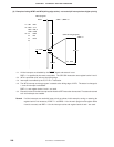
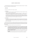
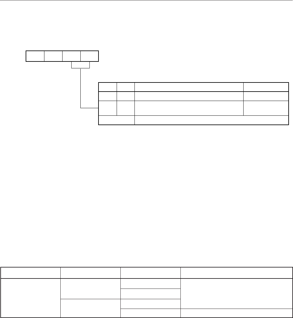
Figure 7-11. Format of INT2 Edge Detection Mode Register (IM2)
3210
IM20IM2100
Address
IM2
FB6H
Symbol
IM21
INT2 test source
IM20
0
Assigned nothing
0
01
Other
Test input pin
–
KR4-KR7Inputs falling edge of any of KR4/P70 to
KR7/P73 pin
Setting prohibited
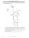
Cautions1. If the contents of the edge detection mode register are changed, the test request flag may be
set. Disable the test input before changing the contents of the mode register. Then, clear the
test request flag by the CLR1 instruction and enable the test input.
2. If a low level is input to even one of the KR×
pins, IRQ2 is not set even if the falling edge is
input to the other pins.
3. On reset, all bits of IM2 become 0. For this reason, nothing is assigned as the N2 test source.
When performing an interrupt using a falling edge input on any of pins KR4 to KR7, IM2 must
be set to 0001B.
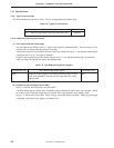
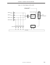
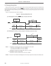
(3) KRREN pin functions
In the STOP mode, when the KRREN pin is high, and a falling edge input is generated any of pins KR4 to
KR7, a system reset occurs.
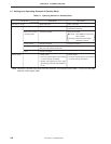
Table 7-7. KR4 to KR7 Pins, KRREN Pin and Test Function
Pins KR4-KR7 Operating Mode KRREN Pin Test Function
Falling edge signal Normal operating and Low Set IRQ2
generated HALT mode High
STOP mode Low
High Disabled for system reset
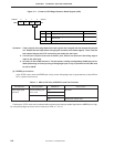
Furthermore, STOP mode can be released without altering the interrupt enable flag when the KRREN pin is high,
by using falling edge input (key return reset) at pin KRn (n = 4 to 7).