


CHAPTER 6 PERIPHERAL HARDWARE FUNCTION
108 User’s Manual U10676EJ3V0UM
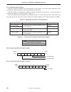
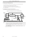
X1
X2
V
SS
Crystal or ceramic
resonator
PD754244
µ
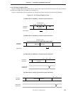
X1
X2
External
clock
PD754244
µ
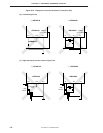
(2) System clock oscillator
(a)
µ
PD754144 (RC oscillation)
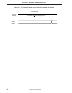
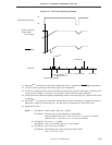
The system clock oscillator oscillates by means of a resistor (R) and capacitor (C) connected to the CL1
and CL2 pins.
An external clock cannot be input for RC oscillation.
The relationship between the output frequency of the system clock oscillator (f
CC), resistance (R), and
capacitance (C) is as follows.
1
f
CC =
2RC
Cautions f
CC may have a frequency deviation due to fluctuation of the supply voltage or
temperature.
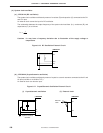
Figure 6-16. RC Oscillation External Circuit
CL1
CL2
V
SS
PD754144
µ
(b)
µ
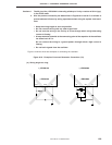
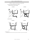
PD754244 (Crystal/ceramic oscillation)
The system clock oscillator oscillates by means of crystal or ceramic resonator connected to the X1 and
X2 pins (6.0 MHz or 4.19 MHz TYP.).
An external clock can also be input.
Figure 6-17. Crystal/Ceramic Oscillation External Circuit
(i) Crystal/ceramic oscillation (ii) External clock