


CHAPTER 6 PERIPHERAL HARDWARE FUNCTION
154 User’s Manual U10676EJ3V0UM
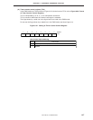
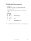
(2) Time setting of timer counter
[Timer set time] (cycle) is calculated by dividing [contents of modulo register + 1] by [count pulse (CP)
frequency] selected by the mode register.
T (sec) = = (n+1)
(resolution)
where,
T (sec): Timer set time (seconds)
f
CP (Hz): CP frequency (Hz)
n: Contents of modulo register (n ≠ 0)
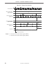
Once the timer has been set, interrupt request flag IRQT2 is set at the set time interval of the timer.
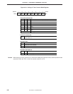
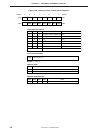
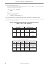
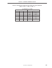
Table 6-8 shows the resolution of each count pulse of the timer counter and the longest set time (time when FFH
is set to the modulo registers 1 and 2).
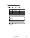
Table 6-8. Resolution and Longest Set Time (16-Bit Timer Counter Mode) (1/2)
(TM10 = 0, TM11 = 1, TM20 = 0, TM21 = 1)
(a)
µ
PD754144: at 1.0 MHz
Mode Register 16-Bit Timer Counter
TM26 TM25 TM24 Resolution Longest Set Time
0102
µ
s 131 ms
0111
µ
s 65.5 ms
1 0 0 1024
µ
s 67.1 s
1 0 1 256
µ
s 16.8 s
11064
µ
s 4.19 s
11116
µ
s 1.05 s
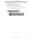
(b)
µ
PD754244: at 6.0 MHz
Mode Register 16-Bit Timer Counter
TM26 TM25 TM24 Resolution Longest Set Time
0 1 0 333 ns 21.8 ms
0 1 1 167 ns 10.9 ms
1 0 0 171
µ
s 11.2 s
1 0 1 42.7
µ
s 2.80 s
1 1 0 10.7
µ
s 699 ms
1 1 1 2.67
µ
s 175 ms
n+1
f
CP
.