


CHAPTER 3 FEATURES OF ARCHITECTURE AND MEMORY MAP
36 User’s Manual U10676EJ3V0UM
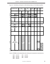
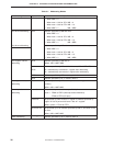
Table 3-1. Addressing Modes
Addressing Mode Representation Specified Address
• When MBE = 0
When mem = 00H to 7FH: MB = 0
When mem = 80H to FFH: MB = 15
• When MBE = 1: MB = MBS
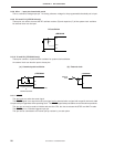
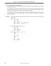
4-bit direct addressing mem Address specified by MB and mem.
• When MBE = 0
When mem = 00H to 7FH: MB = 0
When mem = 80H to FFH: MB = 15
• When MBE = 1: MB = MBS
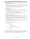
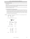
8-bit direct addressing Address specified by MB and mem (mem is even address)
• When MBE = 0
When mem = 00H to 7FH: MB = 0
When mem = 80H to FFH: MB = 15
• When MBE = 1: MB = MBS
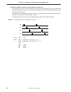
4-bit register indirect @HL Address specified by MB and HL.
addressing Where, MB = MBE MBS
@HL+ Address specified by MB and HL. However, MB = MBE
MBS.
@HL– HL+ automatically increments L register after addressing.
HL– automatically decrements L register after addressing.
@DE Address specified by DE in memory bank 0
@DL Address specified by DL in memory bank 0
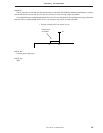
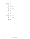
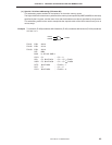
8-bit register indirect @HL Address specified by MB and HL (contents of L register are even
addressing number)
Where, MB = MBE MBS
Bit manipulation fmem.bit Bit specified by bit at address specified by fmem
addressing fmem = FB0H to FBFH (interrupt-related hardware)
FF0H to FFFH (I/O port)
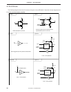
pmem.@L Bit specified by lower 2 bits of L register at address specified by
higher 10 bits of pmem and lower 2 bits of L register.
Where, pmem = FC0H to FFFH
@H+mem.bit Bit specified by bit at address specified by MB, H, and lower 4 bits
of mem.
Where, MB = MBE MBS
Stack addressing — Address specified by SP in memory bank 0
.
.
.
.