


CHAPTER 6 PERIPHERAL HARDWARE FUNCTION
147
User’s Manual U10676EJ3V0UM
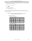
(b) Timer counter control register (TC2)
In the PWM mode, set TC2 as shown in Figure 6-37 (for the format of TC2, refer to Figure 6-30 Format
of Timer Counter Control Register).
TC2 is manipulated by an 8-, 4-, or bit manipulation instruction.
TC2 is cleared to 00H when the internal reset signal is asserted.
The flags shown by a solid line in the figure below are used in the PWM mode.
Do not use the flags shown by a dotted line in the PWM mode (set these flags to 0).
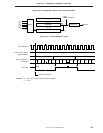
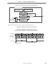
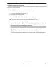
Figure 6-37. Setting of Timer Counter Control Register
765432
10
NRZNRZBTOE2 REMC–––0
TC2
Symbol
Timer counter output enable flag
TOE2
0
1
Disabled (low-level output)
Enabled
Timer output