


CHAPTER 6 PERIPHERAL HARDWARE FUNCTION
127
User’s Manual U10676EJ3V0UM
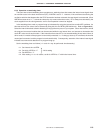
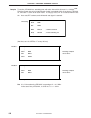
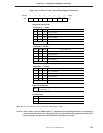
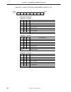
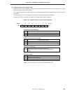
Figure 6-26. Format of Timer Counter Mode Register (Channel 0)
Note Be sure to clear bits 0 and 1 to 0 when setting data to TM0.
Caution After a reset, all bits of TM0 become "0", therefore when operating the timer it is necessary to
set the count pulse value first. Moreover, when any value other than the above is written to CP,
the count pulse set becomes 0 and TM0 does not operate as a timer.
765432
10
PD754244: f
X
= 6.0 MHz
0
Note
0
Note
TM03 TM02TM04TM05TM06–
Address
TM0
FA0H
Symbol
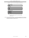
Count pulse (CP) select bit
TM06
Count pulse (CP)
TM05
1
f
X
/2
10
(5.86 kHz)
0
f
X
/2
8
(23.4 kHz)
0
1
11
1
f
X
/2
4
(375 kHz)
1
Setting prohibited
f
X
/2
6
(93.8 kHz)
Other
TM04
0
1
0
1
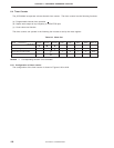
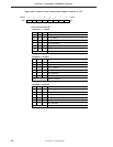
PD754244: f
X
= 4.19 MHz
TM06
Count pulse (CP)
TM05
1
f
X
/2
10
(4.10 kHz)
0
f
X
/2
8
(16.4 kHz)
0
1
11
1
f
X
/2
4
(262 kHz)
1
Setting prohibited
f
X
/2
6
(65.5 kHz)
Other
TM04
0
1
0
1
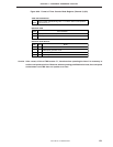
TM03
Clears counter and IRQT0 flag when "1" is written. Starts count operation
if bit 2 is set to "1".
Timer start command bit
Operation mode
TM02
0
1
Stops (count value retained)
Count operation
Count operation
µ
µ
PD754144: f
CC
= 1.0 MHz
TM06
Count pulse (CP)
TM05
1
f
CC
/2
10
(977 Hz)
0
f
CC
/2
8
(3.91 kHz)
0
1
11
1
f
CC
/2
4
(62.5 kHz)
1
Setting prohibited
f
CC
/2
6
(15.6 kHz)
Other
TM04
0
1
0
1
µ