


CHAPTER 6 PERIPHERAL HARDWARE FUNCTION
162 User’s Manual U10676EJ3V0UM
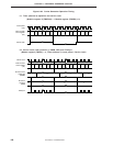
(b) Timer counter control register (TC2)
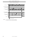
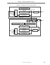
In the CG mode, set the timer counter output enable flag (TOE1) and TC2 as shown in Figure 6-45 (for
the format of TC2, refer to Figure 6-30 Format of Timer Counter Control Register).
TOE1 is manipulated by a bit manipulation instruction. TC2 is manipulated by an 8-, 4-, or bit manipulation
instruction.
TOE1 and TC2 are cleared to 00H when the internal reset signal is asserted.
The flags shown by a solid line in the figure below are used in the CG mode.
Do not use the flags shown by a dotted line in the CG mode (clear these flags to 0).
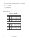
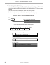
Figure 6-45. Setting of Timer Counter Output Enable Flag
Address
TOE1FAAH
0
Disabled
1
Enabled
Timer counter output enable flag (W)
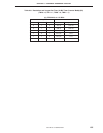
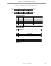
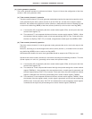
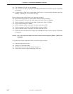
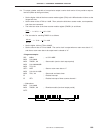
Figure 6-46. Setting of Timer Counter Control Register
–0
NRZB
Area to store no return zero data to be output next. Transferred to NRZ
when timer counter (channel 1) interrupt occurs
No return zero buffer flag
No return zero flag
NRZ
0
1
Outputs low level to PTO2 pin (Carrier clock stopped)
Outputs carrier pulse to PTO2 pin
No return zero data
Remote controller output control flag
REMC
0
1
Outputs carrier pulse to PTO2 pin when NRZ = 1
Outputs high level to PTO2 pin when NRZ = 1
NRZNRZBTOE2 REMC––
TC2
Symbol
Remote controller output
67013245