


CHAPTER 6 PERIPHERAL HARDWARE FUNCTION
129
User’s Manual U10676EJ3V0UM
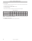
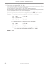
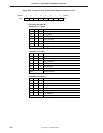
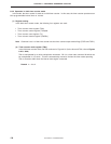
Figure 6-27. Format of Timer Counter Mode Register (Channel 1) (2/2)
TM13
Clears counter and IRQT1 flag when "1" is written. Starts count operation
if bit 2 is set to "1".
Timer start command bit
Operation mode
TM12
0
1
Stops (count value retained)
Count operation
Count operation
Operation mode select bit
TM11
0
1
8-bit timer counter mode
Note
16-bit timer counter mode
ModeTM10
0
0
Other Setting prohibited
Note This mode is used as a carrier generator mode when used in
combination with TM20, TM21 (=11) of timer counter mode
register (channel 2).
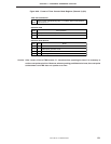
Caution After a reset, all bits of TM1 become "0", therefore when operating the timer it is necessary to
set the count pulse value first. Moreover, when any setting prohibited value is set, the count pulse
set becomes 0 and TM0 does not operate as a timer.