


CHAPTER 6 PERIPHERAL HARDWARE FUNCTION
116 User’s Manual U10676EJ3V0UM
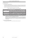
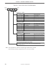
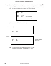
Figure 6-21. Format of Basic Interval Timer Mode Register
Note In the
µ
PD754244 only, wait time is selectable when standby mode is released.
In the
µ
PD754144, wait time is always fixed to 2
9
/fCC (512
µ
s at 1.0 MHz).
3210
BTM0BTM1BTM2BTM3
Address
BTM
F85H
Symbol
PD754244: f
X
= 6.0 MHz
Specifies input clock
f
X
/2
12
(1.46 kHz)
0
f
X
/2
9
(11.7 kHz)
1
1
f
X
/2
7
(46.9 kHz)
0
1
f
X
/2
5
(188 kHz)
1
Other
Setting prohibited
Interrupt interval time (wait time
when standby mode is released)
Note
PD754244: f
X
= 4.19 MHz
Basic interval timer/watchdog timer start control bit
When "1" is written to this bit, the basic interval timer/watchdog timer is started (counter
and interrupt request flag are cleared). When the timer starts operating, this bit is
automatically reset to "0".
1
1
1
00
0 2
20
/f
X
(175 ms)
2
17
/f
X
(21.8 ms)
2
15
/f
X
(5.46 ms)
2
13
/f
X
(1.37 ms)
–
Specifies input clock
f
X
/2
12
(1.02 kHz)
0
f
X
/2
9
(8.19 kHz)
1
1
f
X
/2
7
(32.768 kHz)
0
1
f
X
/2
5
(131 kHz)
1
Other
Setting prohibited
Interrupt interval time (wait time
when standby mode is released)
Note
1
1
1
00
0 2
20
/f
X
(250 ms)
2
17
/f
X
(31.3 ms)
2
15
/f
X
(7.81 ms)
2
13
/f
X
(1.95 ms)
–
PD754144: f
CC
= 1.0 MHz
Specifies input clock
f
CC
/2
12
(244 Hz)
0
f
CC
/2
9
(1.95 kHz)
1
1
f
CC
/2
7
(7.81 kHz)
0
1
f
CC
/2
5
(31.3 kHz)
1
Other
Setting prohibited
Interrupt interval time
1
1
1
00
0 2
20
/f
CC
(1.05 s)
2
17
/f
CC
(131 ms)
2
15
/f
CC
(32.8 ms)
2
13
/f
CC
(8.19 ms)
–
µ
µ
µ