


CHAPTER 3 FEATURES OF ARCHITECTURE AND MEMORY MAP
50 User’s Manual U10676EJ3V0UM
3.3 Memory-Mapped I/O
The
µ
PD754244 employs memory-mapped I/O that maps peripheral hardware units such as I/O ports and timers
to addresses F80H to FFFH on the data memory space, as shown in Figure 3-2. Therefore, no special instructions
to control the peripheral hardware units are provided, and all the hardware units are controlled by using memory
manipulation instructions. (Some mnemonics that make the program easy to read are provided for hardware control.)
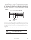
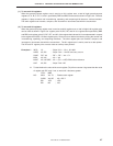
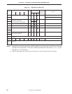
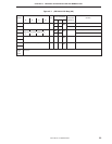
To manipulate peripheral hardware units, the addressing modes shown in Table 3-4 can be used.
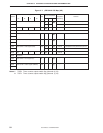
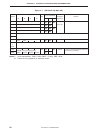
Table 3-4. Addressing Modes Applicable to Peripheral Hardware Unit Manipulation
Applicable Addressing Mode Hardware Units
Bit manipulation Specified in direct addressing mode mem.bit with All hardware units that can be
MBE = 0 or (MBE = 1, MBS = 15) manipulated in 1-bit units
Specified in direct addressing mode fmem.bit regardless IST1, IST0, MBE, RBE
of setting of MBE and MBS IE×××, IRQ×××, PORTn.×
Specified in indirect addressing mode pmem.@L BSBn.×
regardless of setting of MBE and MBS PORTn.×
4-bit manipulation
Specifies in direct addressing mode mem with
MBE = 0 All hardware units that can be
or (MBE = 1
, MBS = 15) manipulated in 4-bit units
Specified in register indirect addressing @HL with
(MBE = 1, MBS = 15)
8-bit manipulation Specified in direct addressing mem with MBE = 0 or All hardware units that can be
(MBE = 1, MBS = 15), where mem is even number. manipulated in 8-bit units
Specified in register indirect addressing @HL with
MBE = 1, MBS = 15, where contents of L register
are even number
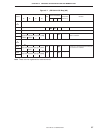
Example CLR1 MBE ; MBE = 0
SET1 TM0. 3 ; Starts timer 0
EI IE0 ; Enables INT0
DI IET1 ; Disables INTT1
SKTCLR IRQ2 ; Tests and clears INT2 request flag
SET1 PORT3, @L ; Sets port 3
IN A, PORT6 ; A ← port 6