


CHAPTER 6 PERIPHERAL HARDWARE FUNCTION
105
User’s Manual U10676EJ3V0UM
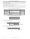
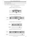
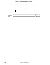
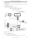
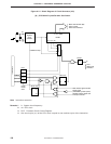
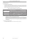
6.2.2 Function and operation of clock generator
The clock generator generates the following types of clocks and controls the operation mode of the CPU in the
standby mode.
• System clock f
X
• CPU clock Φ
• Clock to peripheral hardware
The operation of the clock generator is determined by the processor clock control register (PCC) as follows.
(a) When the RESET signal is asserted, the slowest mode of the system clock
Note 1
is selected (PCC = 0).
(b) The CPU clock can be changed in four steps
Note 2
by PCC.
(c) Two standby modes, STOP and HALT, can be used.
(d) The system clock is divided and supplied to the peripheral hardware units.
Notes 1.
µ
PD754144: 64
µ
s at fCC = 1.0 MHz
µ
PD754244: 15.3
µ
s at fX = 4.19 MHz, 10.7
µ
s at 6.0 MHz
2.
µ
PD754144: 4, 8, 16, 64
µ
s at fCC = 1.0 MHz
µ
PD754244: 0.95, 1.91, 3.81, 15.3
µ
s at fX = 4.19 MHz
0.67, 1.33, 6.67, 10.7
µ
s at fX = 6.0 MHz