


CHAPTER 3 FEATURES OF ARCHITECTURE AND MEMORY MAP
33
User’s Manual U10676EJ3V0UM
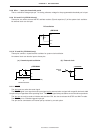
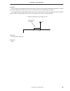
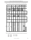
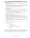
Figure 3-1. Selecting MBE = 0 Mode and MBE = 1 Mode
Internal hardware
and static RAM
manipulation
repeated.
; MBE = 0 by vector table
<Main program>
SET 1 MBE
CLR 1 MBE
MBE
= 1
MBE
= 0
SET 1 MBE
MBE
= 1
<Subroutine>
CLR1 MBE
RET
RETI
MBE = 0
(Interrupt servicing)
MBE = 0
Remark Solid line: MBE = 1, dotted line: MBE = 0
Because MBE is automatically saved or restored during subroutine processing, it can be changed even while
subroutine processing is being executed. MBE can also be saved or restored automatically during interrupt servicing,
so that MBE during interrupt servicing can be specified as soon as the interrupt servicing is started, by setting the
interrupt vector table. This feature is useful for high-speed interrupt servicing.
To change MBS by using subroutine processing or interrupt servicing, save or restore it to the stack by using the
PUSH or POP instruction.
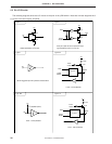
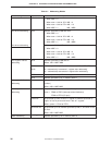
MBE is set by using the SET1 or CLR1 instruction. Use the SEL instruction to set MBS.
Examples 1. To clear MBE and fix memory bank
CLR1 MBE ; MBE ← 0
2. To select memory bank 4
SET1 MBE ; MBE ← 1
SEL MB4 ; MBE ← 4