


CHAPTER 9 RESET FUNCTION
231
User’s Manual U10676EJ3V0UM
9.2 Watchdog Flag (WDF), Key Return Flag (KRF)
WDF and KRF are mapped to bit 2 and 3 of address FC6H respectively.
The contents of WDF and KRF are undefined initially, but they are initialized to “0” by external RESET signal
generation.
WDF is cleared by a watchdog timer overflow signal, and KRF is set by a reset signal generated by the KRn
pin. As a result, by checking the contents of WDF and KRF, it is possible to know what kind of reset signal is
generated.
As WDF and KRF are cleared only by an external signal or instruction execution, once these flags are set, they
are not cleared until an external signal is generated or a clear instruction is executed. Check and clear the contents
of WDF and KRF after the reset start operation by executing the SKTCLR instruction, etc.
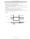
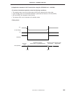
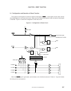
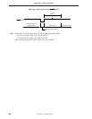
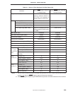
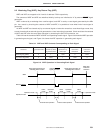
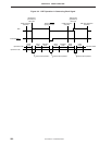
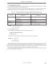
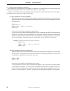
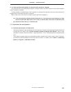
Table 9-2 lists the contents of WDF and KRF corresponding to each signal. Figure 9-3 shows the WDF operation
in generating each signal, and Figure 9-4 shows the KRF operation in generating each signal.
Table 9-2. WDF and KRF Contents Corresponding to Each Signal
External RESET
Reset Signal
Reset Signal WDF Clear KRF Clear
Hardware Signal Generation
Generation by Watch-
Generation by Instruction Instruction
dog Timer Overflow
KRn Input Execution Execution
Watchdog flag (WDF) 0 1 Hold 0 Hold
Key return flag (KRF) 0 Hold 1 Hold 0
Figure 9-3. WDF Operation in Generating Each Signal
External RESET
WDF
Operation mode
Reset signal generation by
watchdog timer overflow
External RESET
signal generation
WDF clear
instruction
execution
Operation mode
HALT
mode
Operation
mode
HALT
mode
Operation
mode
HALT
mode
Operation mode
Internal reset operation Internal reset operation Internal reset operation
Reset signal generation by
watchdog timer overflow