


CHAPTER 3 FEATURES OF ARCHITECTURE AND MEMORY MAP
55
User’s Manual U10676EJ3V0UM
................................................................................
................................................................................
CY
Note 1
SK2
Note 1
SK1
Note 1
SK0
Note 1
INTA register (INTA)
––IEBT IRQBT
INTB register (INTB)
IEEE IRQEE ––
INTE register (INTE)
IET1 IRQT1 IET0 IRQT0
INTF register (INTF)
IET2 IRQT2 ––
INTG register (INTG)
––IE0 IRQ0
INTH register (INTH)
––IE2 IRQ2
................................................................................
................................................................................
................................................................................
................................................................................
................................................................................
................................................................................
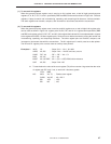
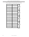
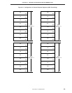
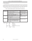
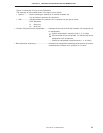
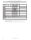
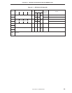
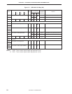
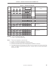
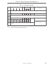
Figure 3-7.
µ
PD754244 I/O Map (4/8)
Hardware name (symbol)
Number of bits that
Bit
Address R/W
can be manipulated
manipulation Remarks
b3 b2 b1 b0 1-bit 4-bit 8-bit
addressing
FB0H
IST1 IST0 MBE RBE
R/W
(R/W) (R/W)
(R) fmem.bit R only possible as 8-bit manipulation.
Program status word (PSW)
Note 2
–
FB2H Interrupt priority selection register (IPS) R/W –
– Note 3
FB3H Processor clock control register (PCC) R/W –
– Note 4
FB4H INT0 edge detection mode register (IM0) R/W –
––
FB5H Unmounted
FB6H INT2 edge detection mode register (IM2)
Note 5
R/W – ––
FB7H Unmounted
FB8H R/W
– fmem.bit Bit manipulation can be performed by
reserved word only.
FB9H R/W
–
FBAH Unmounted
FBBH
FBCH R/W
– fmem.bit Bit manipulation can be performed by
reserved word only.
FBDH R/W
–
FBEH R/W
–
FBFH R/W
–
Remarks 1. IE××× is an interrupt enable flag.
2. IRQ××× is an interrupt request flag.
Notes 1. These are not registered as reserved words.
2. Use the CY manipulation instruction to write to CY.
3. IME (bit 3) can only be manipulated by an EI/DI instruction.
4. PCC3 (bit 3) and PCC2 (bit 2) can be manipulated by a STOP/HALT instruction.
5. This register specifies the falling edge of the KRn pin as the set signal of the interrupt request flag
(IRQ2). This register is initialized to 00H after reset. Therefore, write 01H to set the falling edge of
the KRn pin to IRQ2.