


CHAPTER 6 PERIPHERAL HARDWARE FUNCTION
170 User’s Manual U10676EJ3V0UM
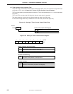
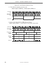
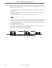
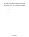
<3> To output a custom code with a 0.56 ms period to output a carrier clock when data is “1”, a 1.69 ms
to output a low level, a 0.56 ms to output a carrier clock when data is “0”, and a 0.56 ms period to output
a low level (refer to the figure below).
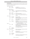
• Set the higher 4 bits of the timer counter mode register (TM1) to 0011B and select 1.95 ms as the
longest set time.
• Set the lower 4 bits of TM1 to 1100B. Then, select the 8-bit timer counter mode, count operation,
and timer start command.
• The initial set value of the timer counter modulo register (TMOD1) is as follows.
– 1 = 73.3 – 1 = 72 = 48H
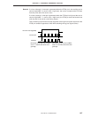
• During the period in which the carrier output of TMOD1 is not performed, processing is executed for
the duration of the same as the output period when data is “0” and for the duration three times that
of the output period when data is “1” (software repeats three times the period in which carrier output
is not performed when data is “0”).
• Set the higher 4 bits of TC2 to 0000B.
• Set the lower 4 bits of TC2 to 0000B. The carrier clock is output when the no return zero data is “1”.
The no return zero data to be output next is cleared to “0”.
• Set the transmit data (“0” or “1”) to the bit sequential buffer.
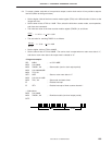
0.56 ms 0.56 ms 0.56 ms1.69 ms
Data "1" Data "0"
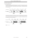
0.56 ms
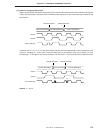
7.64
µ
s