


CHAPTER 8 STANDBY FUNCTION
220 User’s Manual U10676EJ3V0UM
<3> Clear again the IRQ used to release STOP mode to enter STOP mode.
In this STOP mode, IRQ of the selected interrupt is set and HALT mode is entered.
Then, after a wait time, the system returns to the normal operating mode.
In the case of the
µ
PD754244, when the STOP mode has been released by an interrupt, the wait time is determined
by the setting of BTM (refer to Table 8-2).
The time required for the oscillation to stabilize varies depending on the type of oscillator used and the supply
voltage when the STOP mode has been released. Therefore, you should select the appropriate wait time depending
on the given conditions, and set BTM before setting the STOP mode.
µ
PD754144: The wait time is fixed to 2
9
/fCC (512
µ
s at 1.0 MHz)
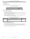
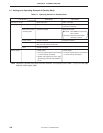
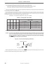
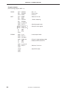
Table 8-2. Selecting Wait Time by BTM
Wait Time
Note
fX = 6.0 MHz fX = 4.19 MHz
–000About 2
20
/fX (about 175 ms) About 2
20
/fX (about 250 ms)
–011About 2
17
/fX (about 21.8 ms) About 2
17
/fX (about 31.3 ms)
–101About 2
15
/fX (about 5.46 ms) About 2
15
/fX (about 7.81 ms)
–111About 2
13
/fX (about 1.37 ms) About 2
13
/fX (about 1.95 ms)
Other than above Setting prohibited
Note This time does not include the time required to start oscillation after the STOP mode has been released.
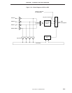
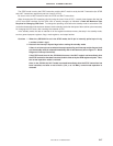
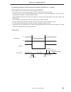
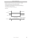
Caution In the case of the
µ
PD754244, the wait time that elapses when the STOP mode has been released
does not include the time that elapses until the clock oscillation is started after the STOP mode
has been released (a in Figure 8-2), regardless of whether the STOP mode has been released by
the RESET signal or occurrence of an interrupt.
Figure 8-2. Wait Time After Releasing STOP Mode
VSS
STOP mode released
Voltage
waveform
of X1 pin
a
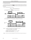
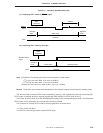
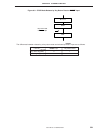
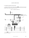
Before releasing STOP mode by a key return reset or RESET input rather than interrupt input, be sure to clear
all interrupt enable flags (including IE2) as shown in Figure 8-3.
BTM3 BTM2 BTM1 BTM0