


CHAPTER 2 PIN FUNCTIONS
25
User’s Manual U10676EJ3V0UM
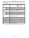
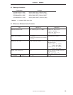
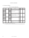
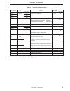
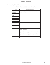
Table 2-2. Functions of Non-Port Pins
Pin Name I/O
Alternate
Function
After Reset
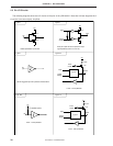
I/O Circuit
Function Type
Note
PTO0 Output P30 Timer counter output pins. Input E-B
PTO1 P31
PTO2 P32
INT0 Input P61 Edge-detected vectored interrupt input Input F -A
(edge to be detected is selectable).
Noise eliminator is selectable.
KR4 to KR7 Input P70 to P73 Falling edge-detected testable input. Input B -A
PTH00 Input P62 Variable threshold voltage 2-bit analog input. Input F -A
PTH01 P63
KRREN Input – Key return reset enable pin. Input B
Reset signal is generated at falling edge of KRn
when KRREN = high in STOP mode.
AVREF Input P60 Reference voltage input pin. Input F -A
CL1 Input – Provided in
µ
PD754144 only. – –
These pins connect R and C for system clock
CL2 Output oscillation. No external clock can be input to
these pins.
X1 Input – Provided in
µ
PD754244 only. – –
These pins connect crystal/ceramic oscillator for
X2 – system clock oscillation. When external clock is
used, input it to X1 and inverse phase to X2.
RESET Input – System reset input pin (active-low) – B -A
IC – – Internally connected. Connect directly to VDD.– –
VDD – – Positive power supply pin. – –
VSS – – Ground potential. – –
Note Circled characters indicate Schmitt triggered input.
Noise
eliminator/
asynchronous
selectable