


CHAPTER 7 INTERRUPT AND TEST FUNCTIONS
195
User’s Manual U10676EJ3V0UM
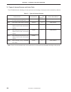
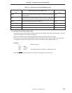
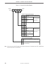
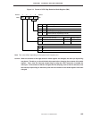
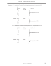
Figure 7-6. Format of INT0 Edge Detection Mode Register (IM0)
3210
IM00IM01IM02IM03
Address
IM0
FB4H
Symbol
IM01
Specifies edge to be detected
IM00
0
Rising edge
0
0
Falling edge
1
1
Both rising and falling edges
0
1
Ignored (interrupt request flag is not set)
1
IM02
Noise eliminator select bit
0
Selects noise eliminator
1
Does not select noise eliminator
Sampling Standby release
Enabled
Disabled
Disabled
Enabled
IM03
Sampling clock
0
Note
1
f
X
/64
Note
Φ
Note This value differs depending on the system clock frequency (fX).
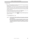
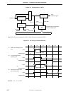
Caution When the contents of the edge detection mode register are changed, the interrupt request flag
may be set. Therefore, you should disable interrupts before changing the contents of the mode
register. Then, clear the interrupt request flag by using the CLR1 instruction to enable the
interrupts. If the contents of IM0 are changed and the sampling clock of f
X/64 is selected, clear
the interrupt request flag 16 machine cycles after the contents of the mode register have been
changed.