


CHAPTER 6 PERIPHERAL HARDWARE FUNCTION
146 User’s Manual U10676EJ3V0UM
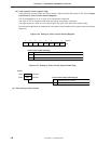
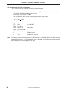
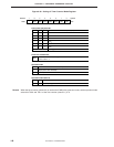
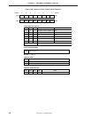
Figure 6-36. Setting of Timer Counter Mode Register
765432
10
TM20TM21TM23 TM22TM24TM25TM26–
Address
TM2
F90H
Symbol
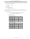
TM23
Clears counter and IRQT2 flag when "1" is written. Starts count operation
if bit 2 is set to "1".
Timer start command bit
Operation mode
TM22
0
1
Stops (count value retained)
Count operation
Count operation
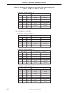
Count pulse (CP) select bit
TM26
Count pulse (CP)
TM25
01
10
01
10
TM24
0
1
0
1
110
111
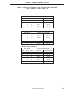
Operation mode select bit
TM21
0 PWM pulse generator mode
ModeTM20
1
f
X
/2
f
X
f
X
/2
8
f
X
/2
6
f
X
/2
10
f
X
/2
4
Other
Setting prohibited
Remark When the timer counter (channel 2) is used as the PWM pulse generator mode, set the operation mode
select bits TM10 and TM11 of the time counter (channel 1) to 0.