


CHAPTER 6 PERIPHERAL HARDWARE FUNCTION
149
User’s Manual U10676EJ3V0UM
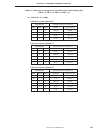
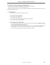
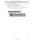
Figure 6-38. PWM Pulse Generator Operating Configuration
Note This is the IRQT2 set signal. It is only set when TMOD2 matches T2.
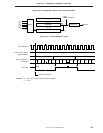
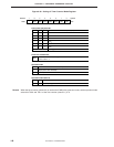
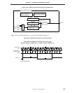
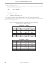
Figure 6-39. PWM Pulse Generator Operating Timing
Timer counter (channel 2) operation and carrier clock
(Modulo register H (TMOD2H) = 1, modulo register (TMOD2) = k)
Count pulse
(CP)
Timer counter
count register
(T2)
TOUT F/F Set
Timer start command
012 i–11012 k–1k0123
Timer counter (channel 2)
High level period setting
timer counter modulo
register (TMOD2H)
Timer counter (Channel 2)
modulo register (TMOD2)
MPX
Comparator
INTT2
Note
Internal
clock
CP
TOUT F/F PTO2
Timer counter count
register (T2)
Clear
MPX
Coinci-
dence
f
x
f
x
/2
f
x
/2
4
f
x
/2
6
f
x
/2
8
f
x
/2
10