


CHAPTER 7 INTERRUPT AND TEST FUNCTIONS
197
User’s Manual U10676EJ3V0UM
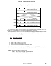
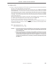
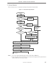
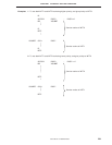
7.4 Interrupt Sequence
When an interrupt occurs, it is processed according to the procedure illustrated below.
Figure 7-7. Interrupt Servicing Sequence
Interrupt (INT×××)
occurs
Sets IRQ×××
IE××× set?
Corresponding VRQn
occurs
Pending until
IE××× is set
NO
YES
IME=1
Pending until
IME is set
NO
Is
VRQn interrupt with
high priority?
YES
YES
Note 1
IST1, 0 = 00 or
01
Note 1
IST1 , 0 = 00
YES
NO
NO
If two or more VRQn occur
simultaneously, one is selected
according to the priority in Table 7-1.
Rest of
VRQn
Pending until
servicing under
execution is
completed
Selected
VRQn
Saves contents of PC and PSW to stack memory and sets
data
Note 2
to PC, RBE, and MBE in vector table corresponding to started VRQn
Updates contents of IST0 and 1 to 01 if they are
00, or to 10 if they are 01
Resets acknowledged IRQ××× (however, if interrupt source
shares vector address with other interrupt, refer to 7.6)
Jumps to interrupt service program servicing
start address
YES
NO
Notes 1. IST1 and 0: Interrupt status flags (bits 3 and 2 of PSW; Refer to Table 7-3.)
2. Each vector table stores the start address of an interrupt service program and the preset values of
MBE and RBE when the interrupt is started.