


24 User’s Manual U10676EJ3V0UM
CHAPTER 2 PIN FUNCTIONS
2.1 Pin Functions of
µ
PD754244
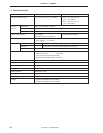
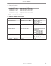
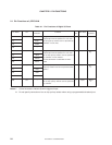
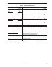
Table 2-1. Pin Functions of Digital I/O Ports
Pin Name I/O
Alternate
Function
8-Bit
After Reset
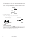
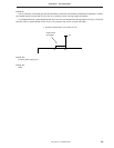
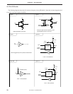
I/O Circuit
Function I/O Type
Note 1
P30 I/O PTO0 × Input E-B
P31 PTO1
P32 PTO2
P33 –
P60 I/O AVREF × Input F -A
P61 INT0
P62 PTH00
P63 PTH01
P70 Input KR4 × Input B -A
P71 KR5
P72 KR6
P73 KR7
P80 I/O – × Input F -A
Notes 1. Circled characters indicate Schmitt-triggered input.
2. Do not specify connection of an on-chip pull-up resistor when using a programmable threshold port.
Programmable 4-bit I/O port (Port 3).
Input/output can be specified in 1-bit units.
On-chip pull-up resistor can be specified by
software in 4-bit units.
Programmable 4-bit I/O port (Port 6).
Input/output can be specified in 1-bit units.
An on-chip pull-up resistor can be specified
by software in 4-bit units
Note 2
.
A noise eliminator is selectable for P61/
INT0.
4-bit input port (Port 7).
A pull-up resistor can be incorporated (mask
option).
1-bit I/O port (PORT8).
An on-chip pull-up resistor can be specified
by software.