


CHAPTER 7 INTERRUPT AND TEST FUNCTIONS
191
User’s Manual U10676EJ3V0UM
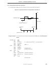
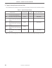
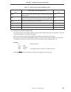
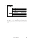
Table 7-2. Signals Setting Interrupt Request Flags
Interrupt Request
Flag
Signal Setting Interrupt Request Flag
Interrupt Enable
Flag
Set by reference time interval signal from basic interval timer
watchdog timer
Set by detection of edge of INT0/P61 pin input signal. Edge to be
detected is selected by INT0 edge detection mode register (IM0)
Set by match signal from timer counter 0
Set by match signal from timer counter 1
Set by match signal from timer counter 2
Set by EEPROM write end signal
IRQBT
IRQ0
IRQT0
IRQT1
IRQT2
IRQEE
IEBT
IE0
IET0
IET1
IET2
IEEE
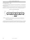
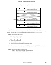
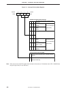
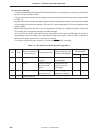
(2) Interrupt priority select register (IPS)
The interrupt priority select register selects an interrupt with a higher priority that can be nested. The lower
3 bits of this register are used for this purpose.
Bit 3 is an interrupt master enable flag (IME) that enables or disables all the interrupts.
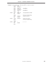
IPS is set by a 4-bit memory manipulation instruction, but bit 3 is set or reset by the EI or DI instruction.
To change the contents of the lower 3 bits of IPS, the interrupt must be disabled (IME = 0).
Example
DI ; Disables interrupt
CLR1 MBE
MOV A, #1001
MOV IPS, A ; Gives higher priority to INTBT and enables interrupt
When the RESET signal is asserted, all the bits of this register are cleared to “0”.