


CHAPTER 6 PERIPHERAL HARDWARE FUNCTION
103
User’s Manual U10676EJ3V0UM
6.2 Clock Generator
The clock generator supplies various clocks to the CPU and peripheral hardware units and controls the operation
mode of the CPU.
6.2.1 Configuration of clock generator
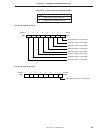
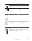
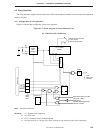
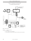
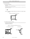
Figure 6-14 shows the configuration of the clock generator.
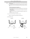
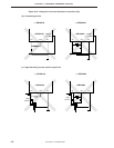
Figure 6-14. Block Diagram of Clock Generator (1/2)
(a)
µ
PD754144 (RC oscillation)
Note Instruction execution
Remarks 1. fCC: System clock frequency
2. Φ = CPU clock
3. PCC: Processor Clock Control Register
4. One clock cycle (t
CY) of the CPU clock is equal to one machine cycle of the instruction.
CL1
CL2
System
clock
oscillator
Oscillation stops
1/1 to 1/4096
1/2 1/4 1/16
f
CC
Divider
1/4 Φ
HALT F/F
S
RQ
S
R
Q
STOP F/F
PCC0
PCC1
PCC2
PCC3
PCC2,
PCC3
clear
HALT
Note
STOP
Note
Wait release signal from BT
(512 s @ 1 MHz)
Reset signal
Standby release signal from
interrupt controller
PCC
4
· Basic interval timer (BT)
· Timer counter
· INT0 noise eliminator
· CPU
· INT0 noise
eliminator
Divider
Selector
Internal bus
µ