


CHAPTER 5 EEPROM
84 User’s Manual U10676EJ3V0UM
5.5.2 Read manipulation
The following procedure is used to read EEPROM.
EWST, ERE and EWE can be set simultaneously by an 8-bit memory manipulation instruction to EWC.
<1> Check that the write status flag (EWST) is 0 (write enabled = writing is currently not being performed).
<2> Set the write enable/disable control bit (EWE) to 0 (write disabled).
<3> Execute the read instruction.
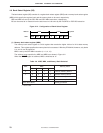
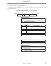
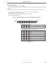
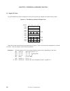
Figure 5-2. EEPROM Write Control Register in EEPROM Read Manipulation
ERE
7
EWTC6
6
EWTC5
5
EWTC4
4
EWE
3
EWST
2
–
1
–
0
FCEH
Address
EWC
Symbol
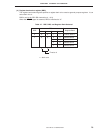
Operating mode selection bit
ERE EWE EWST Mode
1 0 0 EEPROM read enable mode
Cautions 1. Be sure to check that EWST is 0 before reading. If an EEPROM read instruction is executed
during an EEPROM write operation, the value read becomes undefined.
2. There are restrictions on the read instruction. Refer to 5.5.1 EEPROM manipulation
instructions for details.
3. Setting ERE to 1 enables EEPROM read and increases the current consumption. Therefore,
set ERE to 0 when EEPROM is not being read.
4. Execute the read instruction approximately 15
µ
s or more after setting ERE.
5. Setting EWE to 1 enables EEPROM write and increases the current consumption.
Therefore, set EWE to 0 when EEPROM is not being written to.
Example After checking the write status flag (EWST), 8-bit data (0A, 0BH of memory bank 4) is read.
SET1 MBE
SEL MB15
SKF EWST
BR A2
SEL MB4
MOV XA, #0AH
MOV HL, @HL