


CHAPTER 2 PIN FUNCTIONS
27
User’s Manual U10676EJ3V0UM
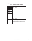
2.2.4 INT0 ... input pin shared with port 6
This pin inputs the vectored interrupt signal detected by the edge. A noise eliminator is selectable for INT0. The
edge to be detected can be specified by using the edge detection mode register (IM0).
(1) INT0 (bits 0 and 1 of IM0)
(a) Active at rising edge
(b) Active at falling edge
(c) Active at both rising and falling edges
(d) External interrupt signal input disabled
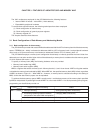
INT0 is an asynchronous input pin, and a signal having a specific high-level width input to this pin can be
acknowledged as an interrupt, regardless of the operating clock of the CPU. In addition, an internal noise
eliminator can be connected to this pin by software, and the sampling clock that is used for noise elimination
can be changed in two steps. In this case, the width of the signal that can be acknowledged differs depending
on the CPU operating clock.
When the RESET signal is asserted, IM0 is cleared to “0”, and the rising edge is selected as the active edge.
INT0 can be used to release the STOP and HALT modes. However, when the noise eliminator is selected,
INT0 cannot be used to release the STOP and HALT modes.
INT0 is a Schmitt-triggered input pin.
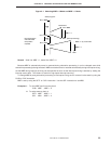
2.2.5 KR4 to KR7 ... input pins shared with port 7
These are key interrupt input pins. KR4 to KR7 are parallel falling edge-detected interrupt input pins.
The interrupt source can be specified for “KR4 to KR7” by using the edge detection mode register (IM2).
When the RESET signal is asserted, these pins serve as port 7 pins and are set to the input mode.
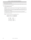
2.2.6 KRREN
This is a key return reset function selection pin. It is always set to input.
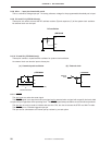
When the KRREN pin is high and it is in STOP mode, a falling input on pins KR4/P70 to KR7/P73 generates a
system reset. At this time, STOP mode is released.
When the KRREN pin is low, pins KR4/P70 to KR7/P73 function as normal input pins or release standby.
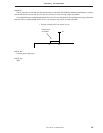
2.2.7 TH00 and TH01 ... input pins shared with port 6
These are the input pins of the programmable threshold port (threshold voltage variable analog input port).
Setting the programmable threshold port mode register (PTHM) can change the threshold voltage in 16 stages.