


CHAPTER 6 PERIPHERAL HARDWARE FUNCTION
159
User’s Manual U10676EJ3V0UM
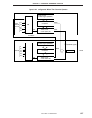
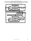
(4) Application of 16-bit timer counter mode
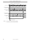
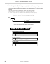
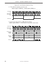
As an interval timer that generates an interrupt at 5-second intervals
Note
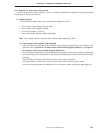
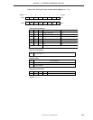
• Set the higher 4 bits of the mode register (TM1) to 0010B, and select the overflow of timer counter
count register (T2).
• Set the higher 4 bits of TM2 to 0100B and select 16.0 second as the longest set time.
• Set the lower 4 bits of TM1 to 0010B and select the 16-bit timer counter mode.
• Set the lower 4 bits of TM2 to 1110B, select the 16-bit timer counter mode and count operation. Then,
issue the timer start command.
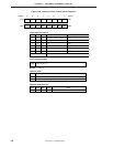
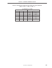
• The set values of the timer counter modulo registers (TMOD1 and TMOD2) are as follows.
= 20491.8 – 1 500BH
<Program example>
SEL MB15 ; or CLR1 MBE
MOV XA, #050H
MOV TMOD1, XA ; Sets modulo (higher 8 bits)
MOV XA, #00B
MOV TMOD2, XA ; Sets modulo (lower 8 bits)
MOV XA, #00100010B
MOV TM1, XA ; Sets mode
MOV XA, #01001110B
MOV TM2, XA ; Sets mode and starts timer
DI IET1 ; Disables timer (channel 1) interrupt
EI ; Enables interrupts
EI IET2 ; Enables timer (channel 2) interrupt
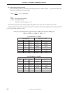
Note This example applies to the operation of the
µ
PD754244 at fX = 4.19 MHz. With fX = 6.0 MHz
operation of the
µ
PD754244 and fCC = 1.0 MHz operation of the
µ
PD754144, the longest set time
and interval time are different even if the settings are the same.
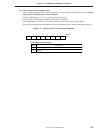
5 sec
244
µ
s