


CHAPTER 6 PERIPHERAL HARDWARE FUNCTION
163
User’s Manual U10676EJ3V0UM
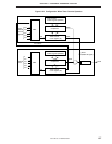
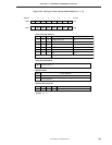
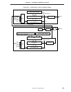
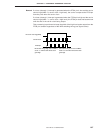
(2) Carrier generator operation
The carrier generator operation is performed as follows. Figure 6-47 shows the configuration of the timer
counter in the carrier generator mode.
(a) Timer counter (channel 1) operation
The timer counter (channel 1) in carrier generator mode determines the time required to output the carrier
clock generated by the timer counter (channel 2) to the PTO2 pin, and the time to stop the output.
Moreover, the overflow time of the timer counter (channel 1) determines the interval of loading from the
no return zero buffer flag (NRZB) of the timer counter (channel 2) to the no return zero flag (NRZ).
<1> A count pulse (CP) is selected by the timer counter mode register (TM1), and is input to the timer
counter count register (T1).
<2> The contents of T1 are compared with those of the timer counter modulo register (TMOD1). When
the contents of the two registers match, an interrupt request flag (IRQT1) is set. At the same time,
the timer out flip-flop (TOUT F/F) is inverted, and generates reload signal from NRZB to NRZ.
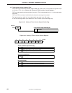
(b) Timer counter (channel 2) operation
The timer counter (channel 2) in carrier generator mode generates the carrier clock to be output to the
PTO2 pin.
Moreover, according to an overflow signal of the timer counter (channel 1), it reloads from the no return
zero buffer flag (NRZB) to the no return zero flag (NRZ).
NRZ determines whether the carrier clock generated should be output to the PTO2 pin or not.
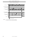
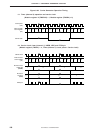
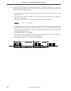
Operation of the timer counter (channel 2) is carried out according to the following procedure. The timer
counter repeats <2> and <3>, generating carrier waves until operation stops.
<1> A count pulse (CP) is selected by the timer counter mode register (TM2), and is input to the timer
counter count register (T2).
<2> The contents of T2 are compared with those of the high-level period setting timer counter modulo
register (TMOD2H). If the contents of the two registers match, a match signal is generated, and
the timer output flip-flop (TOUT F/F) is inverted. At the same time, the count comparison modulo
register is switched to the low-level period setting timer counter modulo register (TMOD2).
<3> The contents of T2 are compared with those of the timer counter modulo register (TMOD2). When
the contents of the two registers match, a match signal is generated, and an interrupt request flag
(IRQT2) is set. At the same time, TOUT F/F is inverted and the count comparison modulo register
is switched to the high-level period setting timer counter modulo register (TMOD2H).