


CHAPTER 6 PERIPHERAL HARDWARE FUNCTION
133
User’s Manual U10676EJ3V0UM
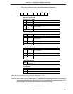
(3) Timer counter control register (TC2)
The timer counter control register (TC2) is an 8-bit register that controls the timer counter (channel 2). Figure
6-30 shows the format of this register.
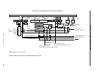
This register controls timer output enable carrier generator mode used in combination with the timer counter
(channel 1).
TC2 is set by an 8- or 4-bit manipulation instruction and bit manipulation instruction.
All the bits of TC2 are cleared to 0 when the internal reset signal is asserted.
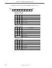
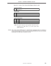
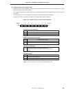
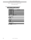
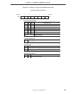
Figure 6-30. Format of Timer Counter Control Register
765432
10
NRZNRZBTOE2 REMC–––0
Note
Address
TC2
F92H
Symbol
No return zero flag
NRZ
0
1
Outputs low level to PTO2 pin
Outputs carrier pulse to PTO2 pin
No return zero data
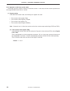
Timer counter output enable flag
TOE2
0
1
Disabled (low level output)
Enabled
Timer output
Remote controller output control flag
REMC
0
1
Outputs carrier pulse to PTO2 pin when NRZ = 1
Outputs high level to PTO2 pin when NRZ = 1
Remote controller output
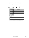
No return zero buffer flag
NRZB
Area to store no return zero data to be output next.
Transferred to NRZ when interrupt of timer counter (channel 1)
occurs
Note Be sure to clear bits 7 to 0 when setting data to TC2.