


CHAPTER 7 INTERRUPT AND TEST FUNCTIONS
206 User’s Manual U10676EJ3V0UM
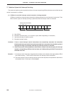
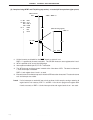
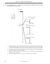
(2) Example of using INTBT and INT0 (falling edge active): not nested (all interrupts have higher priority)
SEL
<1>
Reset
INT0
<4>
RB2
MOV
MOV
CLR1
<2>
A, #1
IM0, A
IRQ0
EI
EI
EI
EI
.
.
.
.
.
.
.
.
.
.
.
.
.
.
.
.
.
.
.
.
.
.
.
.
.
IEBT
IE0
IET0
<3>
Status 0
Status
Status 1
RETI
<5>
(INT0 servicing program)
; RBE = 1, MBE = 0
; RBE = 0
<Main program>
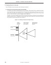
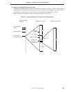
<1> All the interrupts are disabled by the RESET signal and status 0 is set.
RBE = 1 is specified by the reset vector table. The SEL SB2 instruction uses register banks 2 and 3.
<2> INT0 is specified to be active at the falling edge.
<3> Interrupts are enabled by the EI, EI IE××× instruction.
<4> The INT0 interrupt servicing program is started at the falling edge of INT0. The status is changed to
1, and all interrupts are disabled.
RBE = 0, and register banks 0 and 1 are used.
<5> Execution returns from the interrupt routine when the RETI instruction is executed. The status is returned
to 0 and interrupts are enabled.
Remark If all the interrupts are used with lower priority as shown in this example, saving or restoring the
register bank is not necessary if RBE = 1 and RBS = 2 for the main program and register banks
2 and 3 are used, and RBE = 0 for the interrupt routine and register banks 0 and 1 are used.