


CHAPTER 7 INTERRUPT AND TEST FUNCTIONS
196 User’s Manual U10676EJ3V0UM
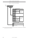
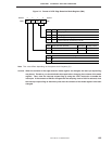
(4) Interrupt status flag
The interrupt status flags (IST0 and IST1) indicate the status of the processing currently being executed by
the CPU and are included in PSW.
The interrupt priority controller controls nesting of interrupts according to the contents of these flags as shown
in Table 7-3.
Because IST0 and IST1 can be changed by using a 4-bit or bit manipulation instruction, interrupts can be nested
with the status under execution changed. IST0 and IST1 can be manipulated in 1-bit units regardless of the
setting of MBE.
Before manipulating IST0 and IST1, be sure to execute the DI instruction to disable interrupts. Execute the
EI instruction after manipulating the flags to enable interrupts.
IST1 and IST0 are saved to the stack memory along with the other flags of PSW when an interrupt is
acknowledged, and their statuses are automatically changed one higher. When the RETI instruction is
executed, the original values of IST1 and IST0 are restored.
The contents of these flags are cleared to “0” when the RESET signal is asserted.
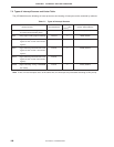
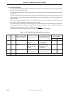
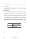
Table 7-3. IST1 and IST0 and Interrupt Servicing Status
IST1 IST0 Processing by CPU
0 0 Status 0 0 1
0 1 Status 1 1 0
1 0 Status 2 ––
1 1 Setting prohibited
After Interrupt
Acknowledged
IST1 IST0
Status of Processing
under Execution
Interrupt Request That
Can Be Acknowledged
Executes normal
program
All interrupts can be
acknowledged
Services interrupt
with low or high
priority
Interrupt with high
priority can be ac-
knowledged
Services interrupt
with high priority
Acknowledging all
interrupts is disabled