


CHAPTER 6 PERIPHERAL HARDWARE FUNCTION
106 User’s Manual U10676EJ3V0UM
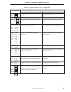
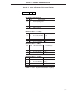
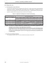
(1) Processor clock control register (PCC)
PCC is a 4-bit register that selects the CPU clock Φ with the lower 2 bits and controls the CPU operation mode
with the higher 2 bits (refer to Figure 6-15).
When either bit 3 or 2 of this register is set to “1”, the standby mode is set. When the standby mode has been
released by the standby release signal, both the bits are automatically cleared and the normal operation mode
is set (for details, refer to CHAPTER 8 STANDBY FUNCTION).
The lower 2 bits of PCC are set by a 4-bit memory manipulation instruction (clear the higher 2 bits to “0”).
Bits 3 and 2 are set to “1” by the STOP and HALT instructions, respectively.
The STOP and HALT instructions can always be executed regardless of the contents of MBE.
Examples 1. To set the fastest machine cycle mode
Note 1
SEL MB15
MOV A, #0011B
MOV PCC, A
2. To set the machine cycle of the
µ
PD754244 to 1.33
µ
s (fX = 6.0 MHz)
Note 2
SEL MB15
MOV A, #0010B
MOV PCC, A
3. To set STOP mode (be sure to write a NOP instruction after STOP and HALT instructions)
STOP
NOP
PCC is cleared to “0” when the RESET signal is asserted.
Notes 1.
µ
PD754144: 4
µ
s (fCC = 1.0 MHz)
µ
PD754244: 0.67
µ
s (fX = 6.0 MHz), or 0.95
µ
s (fX = 4.19 MHz)
2.
µ
PD754144: 8
µ
s (fCC = 1.0 MHz)
µ
PD754244: 1.91
µ
s (fX = 4.19 MHz)