


CHAPTER 6 PERIPHERAL HARDWARE FUNCTION
164 User’s Manual U10676EJ3V0UM
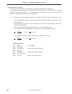
<4> The operations <2> and <3> are repeated.
<5> The no return zero data is reloaded from NRZB to NRZ when timer counter channel 1 generates
an interrupt.
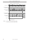
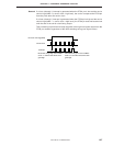
<6> A carrier clock or high level is output when NRZ is set to 1 by the remote controller output flag
(REMC). When NRZ = 0, a low level is output.
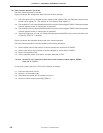
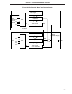
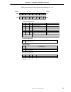
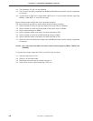
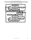
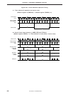
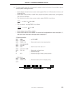
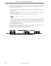
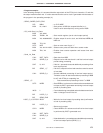
Figure 6-48 shows the timing of the carrier generator operation.
The carrier generator operation is usually started by the following procedure.
<1> Set the number of counts of high-level width of the carrier clock to TMOD2H.
<2> Set the number of counts of low-level width of the carrier clock to TMOD2.
<3> Set the output waveform to REMC.
<4> Set the operation mode, count pulse, and start command to TM2.
<5> Set the number of counts of the NRZ switching timing to TMOD1.
<6> Set the operation mode, count pulse, and start command to TM1.
<7> Set the no return zero data to be output next to NRZB before timer counter channel 1 generates
an interrupt.
Caution Set a value other than 00H to the timer counter modulo registers (TMOD1, TMOD2, and
TMOD2H).
To use the timer counter output pin (PTO1), set the P31 pin as follows.
<1> Clear the output latch of P31.
<2> Set port 3 in the output mode.
<3> Disconnect the internal pull-up resistor from port 3.
<4> Set the timer counter output enable flag (TOE1) to 1.