


CHAPTER 8 STANDBY FUNCTION
217
User’s Manual U10676EJ3V0UM
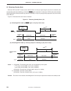
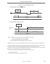
The STOP mode is set by the STOP instruction, and the HALT mode is set by the HALT instruction (the STOP
and HALT instructions respectively set bits 3 and 2 of PCC).
Be sure to write a NOP instruction after the STOP and HALT instructions.
When changing the CPU operating clock by using the lower 2 bits of PCC, a certain time elapses after the bits
of PCC have been rewritten until the CPU clock is actually changed, as indicated in Table 6-5 Maximum Time
Required for Changing CPU Clock. To change the operating clock before the standby mode is set and the CPU
clock after the standby mode has been released, set the standby mode after the lapse of the machine cycles necessary
for changing the CPU clock, after rewriting the contents of PCC.
In the standby mode, the data is retained for all the registers and data memory that stop in the standby mode,
such as general-purpose registers, flags, mode registers, and output latches.
Cautions 1. When the
µ
PD754244 is set in the STOP mode, the X2 pin is internally pulled up to VDD by
a resistor of 50 kΩ (typ.).
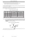
2. Reset all the interrupt request flags before setting the standby mode.
If there is an interrupt source whose interrupt request flag and interrupt enable flag are both
set, the standby mode is released immediately after it has been set (refer to Figure 7-1 Block
Diagram of Interrupt Controller).
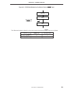
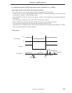
If the STOP mode is set in the
µ
PD754244, however, the HALT mode is set immediately after
the STOP instruction has been executed, and the time set by the BTM register elapses. Then,
the normal operation mode is restored.
Also, in the
µ
PD754144, HALT mode is entered immediately after the STOP instruction has
been executed, and after a wait of 2
9
/fCC (512
µ
s at 1.0 MHz), normal mode operation is
restored.