


CHAPTER 6 PERIPHERAL HARDWARE FUNCTION
180 User’s Manual U10676EJ3V0UM
6.5 Programmable Threshold Port (Analog Input Port)
The
µ
PD754244 provides analog input pins (PTH00, PTH01) whose threshold voltage (reference voltage) is
selectable within sixteen steps. The following operations can be performed with these analog input pins.
(1) Comparator operation
(2) 4-bit resolution A/D converter operation (controlled by software)
Caution When using a programmable threshold port, do not specify connection of an internal pull-up
resistor to port 6.
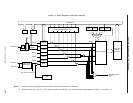
6.5.1 Configuration and operation of programmable threshold port
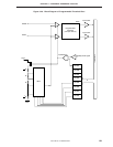
The configuration of the programmable threshold port is shown in Figure 6-49.
The input voltage via the PTH00 and PTH01 pins is compared with the threshold voltage (V
REF) specified by
the programmable threshold port mode (PTHM) register, and the results are stored in the input latch of the
programmable threshold port.
When V
REF > port input voltage: 0
When V
REF < port input voltage: 1
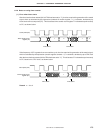
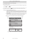
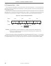
The conversion terminates when the conversion time specified by bit 6 of PTHM has elapsed after setting VREF
by the lower four bits of PTHM, and the conversion result is stored in the input latch of the programmable threshold
port.
As a result, the conversion result must be read after the conversion time specified by bit 6 of PTHM has elapsed
after modifying V
REF by PTHM modification.
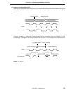
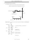
When PCC = 0000B (low-speed operation mode), be sure to clear bit 6 of PTHM to “0” to select a long conversion
time. When PCC = 0010B or 0011B, bit 6 of PTHM can be set to “1” to select the high-speed conversion.
The contents of the input latch can be read or tested by using a memory manipulation instruction, and the
contents of the input latch become undefined by RESET signal generation.