


CHAPTER 6 PERIPHERAL HARDWARE FUNCTION
145
User’s Manual U10676EJ3V0UM
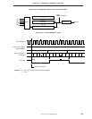
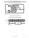
6.4.3 Operation in PWM pulse generator mode (PWM mode)
In this mode, the timer counter (channel 2) is used as a PWM pulse generator.
The timer counter operates as an 8-bit PWM pulse generator.
When the timer counter (channel 2) is used as a PWM pulse generator, the timer counters (channel 0 and 1) can
be used as 8-bit timer counter.
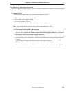
(1) Register setting
In the PWM mode, the following five registers are used.
• Timer counter mode register (TM2)
• Timer counter control register (TC2)
• Timer counter count register (T2)
• Timer counter high-level period setting modulo register (TMOD2H)
• Timer counter modulo register (TMOD2)
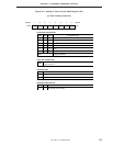
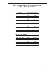
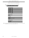
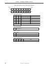
(a) Timer counter mode register (TM2)
In the PWM mode, set TM2 as shown in Figure 6-36 (for the format of TM2, refer to Figure 6-28 Format
of Timer Counter Mode Register (Channel 2)).
TM2 is manipulated by an 8-bit manipulation instruction. Bit 3 is a timer start command bit which can
be manipulated in 1-bit units and is automatically cleared to 0 when the timer starts operating.
TM2 is also cleared to 00H when the internal reset signal is asserted.