


CHAPTER 6 PERIPHERAL HARDWARE FUNCTION
148 User’s Manual U10676EJ3V0UM
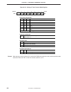
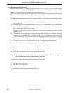
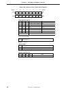
(2) PWM pulse generator operation
The timer counter (channel 2) in PWM pulse generator mode has two registers, a high-level period setting
timer counter modulo register (TMOD2H) and a low-level period setting timer counter modulo register
(TMOD2). Figure 6-38 shows the PWM pulse generator configuration.
Each modulo register inverts its signal when the time set to each elapses. Therefore, pulses output from the
PTO0 pin can be set arbitrarily for each modulo register.
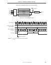
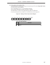
The PWM pulse generator operates as follows. It repeats <2> and <3>, generating pulses until operation stops.
<1> A count pulse (CP) is selected by the timer counter mode register (TM2), and is input to the timer counter
count register (T2).
<2> The contents of T2 are compared with those of the high-level period setting timer counter modulo
register (TMOD2H). If the contents of the two registers match, a match signal is generated, and the
timer output flip-flop (TOUT F/F) is inverted.
The count compare modulo register is switched to the low-level period setting timer counter modulo
register (TMOD2).
<3> The contents of T2 are compared with those of the timer counter modulo register (TMOD2). When the
contents of the two registers match, a match signal is generated, and an interrupt request flag (IRQT2)
is set. At the same time, TOUT F/F is inverted. Then the count compare modulo register is switched
to the high-level period setting timer counter modulo register (TMOD2H).
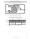
<4> The operations <2> and <3> are alternately repeated, and pulse wave form is generated.
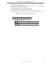
Figure 6-39 shows the timing of the PWM pulse generator operation.
The PWM pulse generator operation is usually started in the following procedure.
<1> Set the number of counts of high-level width to TMOD2H.
<2> Set the number of counts of low-level width to TMOD2.
<3> Set an operation mode, count pulse, and start command to TM2.
Caution Set a value other than 00H to the timer counter modulo register (TMOD2) and high-level
period setting timer counter modulo register (TMOD2H).
To use the timer counter output pin (PTO2), set the P32 pin as follows.
<1> Clear the output latch of P32.
<2> Set port 3 in the output mode.
<3> Disconnect the pull-up resistor from port 3.
<4> Set the timer counter output enable flag (TOE2) to 1.