


Cable Pinouts C - 3
Transceiver Cable Differences
Because AUI Transceiver cables may be built to any of three Ethernet
standards (V1.0, V2.0, and IEEE 802.3), signal differences may occur
between different types of transceiver cables. These three standards also
affect the shielding and grounding of the cables and the size of the wires
used in the cables.
Shielding and Grounding
The most significant difference among AUI cables occurs in the shielding
and grounding of the individual signal and power pairs. IEEE 802.3 and
Ethernet V2.0 specify a requirement for signal isolation due to AC-coupling
of the AUI connection, whereas the V1.0 standard does not include this
requirement.
The three standards specify different techniques for shielding and
grounding:
IEEE 802.3
All shields of the individual signal and power pairs are connected to pin 4.
The overall AUI cable shield is connected to the AUI connector shell to
provide a cable ground. Pin 1 is not used.
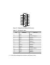
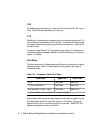
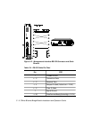
12 DI-B Receive -
13 VP Power +
14 VS Reserved
15 C0-B Reserved
Shell Protective ground Shield terminated to
connector shell
Table C-1. AUI Cable Pin Chart (Continued)