


C - 4 ONline Ethernet Bridge Module Installation and Operation Guide
V2.0
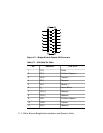
All shields are connected to pin 1 and the AUI connector shell. Pin 4 is not
used. Most Ethernet cables are built this way.
V1.0
Shielding of individual signal or power pairs is not required, since most V1.0
con-trollers and transceivers are DC-coupled. The overall AUI cable shield
provides for shielding and grounding and is connected to pin 1 and the AUI
connector shell.
In practice, most Ethernet V1.0 equipment uses version 2.0 cables due to
cross-talk problems caused by the lack of individual shielding of the pairs in
version 1.0 cables.
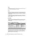
Wire Sizes
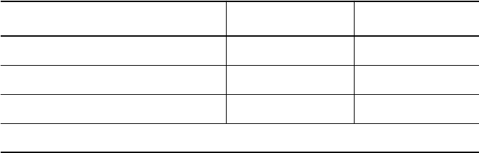
The three versions of AUI cables also use different wire sizes for the signal
and power pairs. Table C-2 describes the wiring used by each type of
transceiver cable.
Signal deterioration along the signal pairs is most likely to happen as the
AUI cable approaches the maximum length of 40 meters. This signal
deterioration is due to the filtering action of the cable. IEEE 802.3 AUI
cables are designed to reduce this effect.
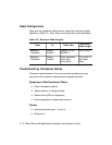
Table C-2. Transceiver Cable Wire Sizes
Cable Type Signal Pair Power Pair
V1.0 AWG #22 AWG #20
V2.0 and IEEE 802.3 AWG #20 AWG #20
Non-standard “Office” cable * AWG #24 * AWG #24 *
* more flexible, but is limited to 5.0 meters in length.