


2 - 4 ONline Ethernet Bridge Module Installation and Operation Guide
Module Front Panel
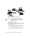
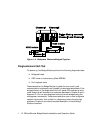
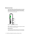
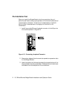
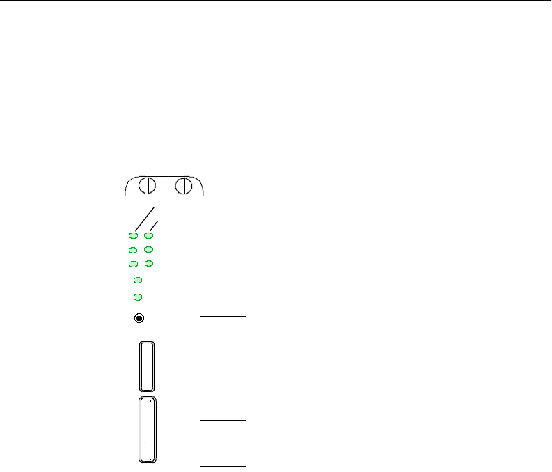
The front panel has eight indicators (LEDs), one button, two connectors,
and the module extractor. The front panel indicators inform you of the
operating state of your Bridge Module. Figure 2-1 shows the Bridge
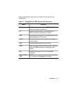
Module front panel and Table 2-1 lists the function of each LED, button,
and connector on the module faceplate.
Figure 2-1. Bridge Module Front Panel
Refer to Appendix D for information on using and interpreting the Bridge
Module front panel controls and indicators.
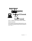
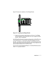
Module Extractor
The module extractor is located at the bottom of the module faceplate.
Use the module extractor to remove the module from the concentrator.
PORT 1
PORT 2
RX
TX
FWD
MGMT
TEST
RESET
AUI
RS-232
SERIAL
PORT
Reset Button
Female AUI Port
RS-232 Serial Port
Module Extractor