


Power-Up Self-Test D - 3
Screen Display
If a terminal is attached to the Management interface, additional
information is displayed on the screen during self-test. As each diagnostic
routine begins, a message appears indicating the name of the routine,
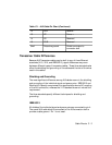
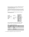
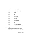
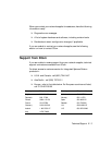
1 1 0 0 0 0 BER (Bus Error Logic)
0 0 1 0 0 0 MFP (Multi-Function Peripheral)
1 0 1 0 0 0 NMI (Non-Maskable Interrupt)
0 1 1 0 0 0 EEPROM
1 1 1 0 0 0 TTY
0 0 0 1 0 0 User
1 0 0 1 0 0 RAM
0 1 0 1 0 0 LANCE1 INTERNAL
1 1 0 1 0 0 LANCE1 Data Transfer
0 0 1 0 0 1 LANCE1 Media
1 0 1 0 0 1 LANCE2 Internal
0 1 1 0 0 1 LANCE2 Data Transfer
1 1 1 0 0 1 LANCE2 Media
0 0 0 0 1 0 Flash
1 0 0 0 1 0 Reset
0 1 0 0 1 0 AF INT (Address Filter Interface)
1 1 0 0 1 0 AF Diagnostic (Address Filter Board Test)
Table 4-1. Diagnostic Code Reference (Continued)
Code Test