


D - 2 ONline Ethernet Bridge Module Installation and Operation Guide
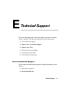
self-test routine results in an error condition, the TEST indicator blinks and
the remaining LEDs display a code indicating which specific test was
running when the error occurred.
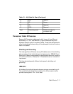
The LED error display uses the top six LEDs on the front panel to create the
Diagnostic Code. These codes are binary representations, where ON is a 1
and OFF is a 0. All of the codes and a brief description are listed in Table
D-1.
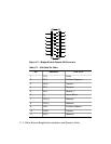
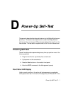
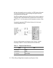
For example, suppose the TEST indicator blinks and the front panel
indicators appear as follows:
The first six LEDs represent the Diagnostic Code, which is “100000".
According to Table D-1, the error occurred within the ROM Test.
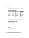
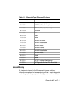
Table 4-1. Diagnostic Code Reference
Code Test
0 0 0 0 0 0 CPU
1 0 0 0 0 0 ROM
0 1 0 0 0 0 Initial Stack