


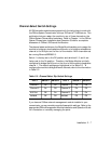
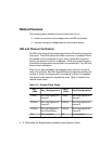

Installation 2 - 11
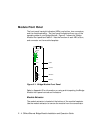
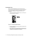
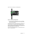
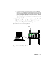
Figure 2-4 shows the installation of the Bridge Module.
Figure 2-4. Installing the Bridge Module
4. Fasten the three spring-loaded screws on the front of the Bridge
Module faceplate to the concentrator with your fingers to provide
ground - do not overtighten.
As the Bridge Module performs its internal diagnostics, the Test LED on the
front panel remains lit. Various LED combinations appear during the
self-test. If the power-up self-test is successful, the Test LED goes off after
approximately 20 seconds and the module returns to the configuration set
up by the dip switches and the TX LED will blink.
If none of the module faceplate LEDs light or if the Test LED blinks, refer to
Table 2-4 for appropriate action.