1 - 12 ONline Ethernet Bridge Module Installation and Operation Guide
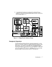
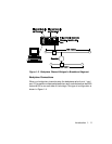
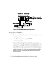
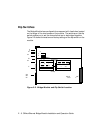
Figure 1-4. Backplane Channels Bridged Together
Diagnostics and Self-Test
On power-up, the Bridge Module performs the following diagnostic tests:
❑ Bridge self-tests
❑ CRC check of code memory (Flash EPROM)
❑ Port loopback tests
These tests allow the Bridge Module to check its own circuitry and
communication interfaces to verify its ability to send and receive data. If the
bridge fails any of the diagnostics, the front panel LEDs indicate an error
code. Power-up self-test and error codes are described in Chapter 5 and in
Appendix D. You can also diagnose local and remote bridges using the
management commands. These commands allow you to view bridge and
network information that is helpful in diagnosing network and bridge
problems. Chapter 4 provides a complete description of each Bridge
Module command.


